|
Thanks for taking the time to look at the CorticalCafe
CGHMaker otherwise known as The Computer Generated Hologram
Construction Kit. With this program and some simple office
supplies, you can make your own holograms without even using a
laser!
This
page has some background information and describes the Cortical Cafe
CGH program functionality, and there are complementary step-by-step
instructions here.
What
is a hologram?
A hologram is a snapshot of "wave-fronts" from a scene. The
hologram records information so that it may be reconstructed in
three-dimensions, whereas a photograph merely records a two-dimensional
projection of the scene. Certain limitations apply to creating
and viewing holograms. In particular:
- Special light - Because holograms depend on
constructive and destructive interference of light waves to recreate
the scene in three-dimensions, light from a laser is usually required
in some capacity. Laser light is special because it is "coherent"
temporally and spatially. This means that all light waves from a
laser have the same "phase", the same "frequency", and usually the beam
remains almost perfectly parallel (doesn't diverge or converge).
You don't always need a laser to view a hologram (though that will give
the cleanest reconstruction), but usually a monochromatic (single
color) point source of illumination works best.
- Motionless environment - Because the light
wave interference must be recorded on film, it is essential that
nothing move, or else the recording will blur and become useless.
The physics of holography stipulate that motion must not exceed 1/4 of
the wavelength of recording light, or about 160 nm (nanometers).
Air currents, sounds, and even expansion of materials due to
temperature changes all have potential to prevent image recording.
Basic holograms come in two flavors:
- Transmission hologram - This hologram is
viewed by placing a light source behind the hologram and looking
through it (like a window). The hologram is recorded in a
two-dimensional format on the film plate.
- Reflection hologram - This hologram is viewed
by looking at the reflection of a light source in the hologram (like a
mirror). This type of hologram depends on the holographic fringes
being recorded in three-dimensions (Bragg refection) on the film plate.
Holograms have some very interesting properties:
- The information in a hologram is distributed -
if you cut it into pieces, you will find that each piece contains
enough information to reconstruct the entire scene.
- Image projection - under some circumstances,
merely shining a laser through the hologram projects an image on to a
screen. No lenses, no optics, nada.
- Viewing directly with a point source - Using a
point source of illumination, a hologram reconstruction presents the
exact same light wavefronts to your eyes that they would receive with
the real object. The hologram is indistinguishable from the
physical object.
Creating
your own hologram
Creating a hologram is both fun and educational. There are quite
a few good sites for learning
about holography or purchasing supplies.
As an alternative to the photochemistry and vibration-free settings
involved with regular holography, this program (launched via the button below) allows you to create
a transmission hologram using just a computer, a laser-printer,
and an overhead transparency. This hologram will behave like one
created using a laser and can be projected or viewed with a point
source.
You create a computer generated hologram using the CorticalCafe
CGHMaker (computer generated hologram construction kit) by specifying
an input file (download sample source files in the precomputed holograms section). The input file defines the source object according
to one of the following methods:
- Use a simple list of points (like pixels,
except we call them voxels because they are points in three-dimensional
space) - Using this method, you can create a hologram of something
simple, like a cube, or a square. The points are defined in XML
using a very simple syntax and may be edited in almost any text
editor. This is the simplest way to define a 3 dimensional
object.
- Create a 2 dimensional GIF image and turn it into
a hologram - Using this method you can turn a word or a picture
into a hologram using a simple paint program. White pixels are
considered "background" while black pixels are considered "points" in
the object. This is the simplest way to define a 2 dimensional
object. I suggest starting with very small (eg, 10x10)
images.
- Create your hologram programmatically using the
Java programming language- This method will allow you to
create objects which are as complex as you desire. You don't need
to be a hard-core programmer to use this method and you do not need
external tools like compilers, development environments or anything
else other than a simple text editor. This is the most
complicated method of defining an object but gives you complete control
over what your reconstructed image should look like.
Sample files demonstrate all three input methods.
What
does the computer generated hologram output look like?
 |
|
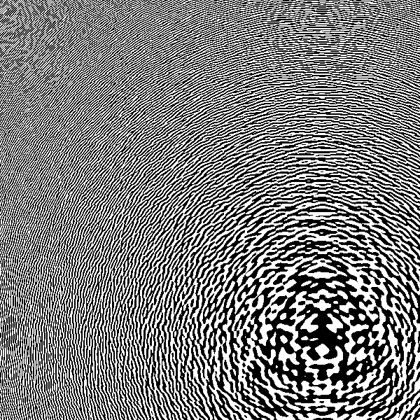
The hologram output is the fringe
pattern of intensity variations that are recorded on the holography
plate. Normally these would be recorded as the constructive and
destructive interference of wavefronts from reference and object beams
at the photographic plate. Since this is a simulation, your
output will be a JPG image containing some representation of the
wavefronts.
If you look at the edge of the CGH pattern, you will see that it varies
black-white-black-etc. with almost every pixel. This means that the
hologram is using maximal output bandwidth. Moving the object off axis
any further will violate nyquist sampling on the output and cause
distortions (ie, aliasing).
|
 |
|
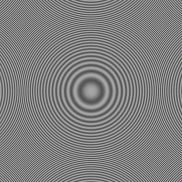
Fresnel Zone Plates... what
fun!
The image on the left is the interference pattern
that occurs between a single point source and a plane-wave at the
photographic plate. Use this
file if you want to calculate the lens yourself.
Since this is essentially a Fresnel lens (though
real lenses usually modulate phase by varying refractive index or lens
thickness), we see a series of cencentric rings with varied spacings
around the center of the image.
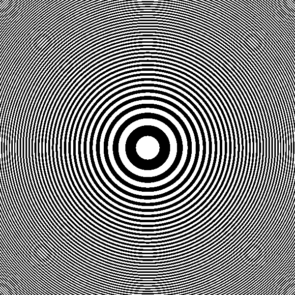
The image on the right demonstrates the
quantization artifacts which occur because of the binary output of the
printer. The multiple smaller circles located symmetrically around the
plate will degrade lens performance.
|
|
 |
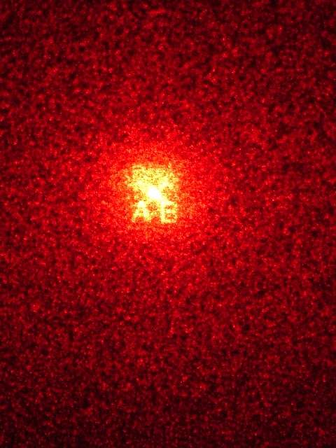
What does the reconstruction look like?
The reconstruction from an image with
the letters "AB" is shown here. The bright spot in the center is
the "DC component", the undiffracted laser beam. Diffraction from
the computed fringes produces a reconstructed image which can, to an
extent, be moved away from the unmodulated beam. Unfortunately,
the modulation produces a similar image with axial symmetry on the
other side of the DC spot, though this could be eliminated with spatial
filtering.
Much of laser beam is used to produce artifact instead of contributing
to the image reconstruction, suggesting low efficiency for the
technique. A number of inaccuracies exist, mostly related to the
output of the fringes. But stop complaining... it works!
By the way, he reconstruction you see here is created simply by shining
a laser-pointer through the hologram. If you use
some simple optics to illuminate a larger part of the hologram or even
a poorly collimated laser it should increase the signal/noise ratio
of the reconstruction. |
|
 |
 |
|
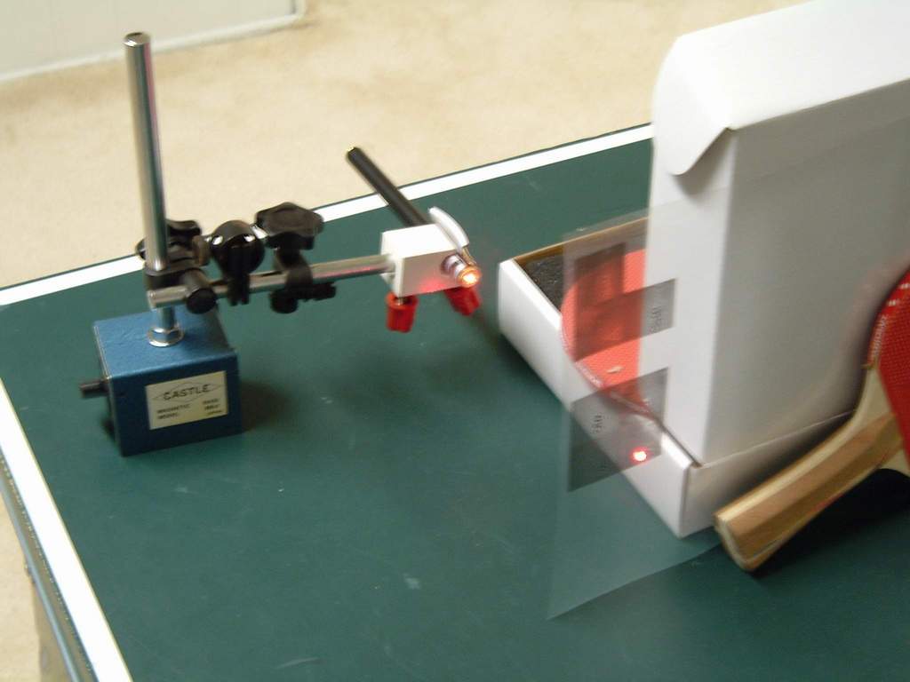
Here is a photo demonstrating the
reconstruction setup. It is simply a laser pointer beam aimed
through the computed fringes which were printed on a
transparency. Since the collimated beam from a laser pointer is
still a few square millimeters, it covers hundreds of plate pixels and
can reconstruct an intelligible image.
Note the ping-pong paddle/box mount holding the transparency.
Similar scientific apparatus may be purchased at a local sporting
retailer if necessary. |
The
CorticalCafe CGHMaker software interface
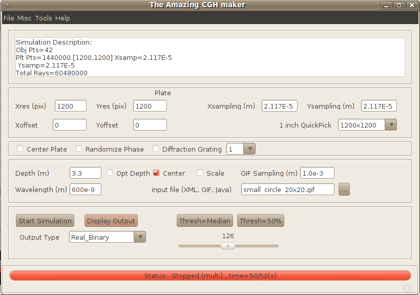
- Plate controls
- x/y resolution
- the number of pixels on the plate
- x/y sampling
- the spacing between pixel centers on the
plate in meters (see spatial sampling rates below)
- x/y offsets
- the offset in meters of the plate from the normal axis of the object
beam
- 1 inch QuickPick
- this is a quick way to set the program to compute a 1-inch hologram
at the most common printer resolutions. For example, if your
printer is 600DPI, then choose 600x600 and the resolution and sampling
fields will automatically be chosen.
- Misc controls
- Center plate
- centers the object with respect to
the X/Y axis of the plate.
- Randomize Phase
- apply random phases across the
object, reduces speckle artifact caused by coherent interaction between
light rays from the object.
- Diffraction grating
- if checked, will produce a
diffraction grating instead of a hologram. Useful to test the
resolution of the output device
- Diffraction
grating multiple - if diffraction
grating is selected, this is related to the order of the grating.
Use "1" for finest fringes to test the resolution of the output device.
- Object controls
- Depth -
defines how far (in meters) along the Z axis an object will be focused
from the plate during reconstruction. For example, if the plate
will be 10 feet away, enter 3.05 (305cm) into this field.
- Opt Depth -
checking this box will compute and use the minimum depth that is
possible without exceeding the resolution of your output device (aka,
aliasing). Uncheck this box if you want to control the
focal distance manually or you have a 3 dimensional object (eg, a JAVA
or XML input file).
- Center -
checking this box centers the object along the normal axis to the
hologram plate. You will almost always want this to occur.
- Scale -
checking this box scales the object to the same size as the hologram
plate, ignoring the GIF sampling field.
- Sampling -
If an image file is used as the object, this defines the spacing (in
meters) along the X/Y axes
of the object. For example, if your image is 10x10 pixels and spacing
is 1e-3, then your image will be 1cm high.
- Wavelength
- defines the wavelength of light (in meters) used
to create the hologram in meters. A value of 630e-9 is typical
for a "red" Helium-Neon (HeNe) laser and close enough to inexpensive
diode-laser pointers (usually 635-658nm).
- Input file
- this field defines the input for the
hologram, and may be a GIF, JAVA or XML file.
- Start/Stop computation -
Starts computation of the
hologram. Processing may take many minutes for a large complex
simulation. Progress is displayed in the status display along
with an estimate of the total time required.
Once the hologram is computed, you may display the output as many times
as you wish using different output algorithms without
recomputing. Pressing this button during a computation aborts
processing.
- Display output
selection - Selects how to display the
output. Since most output methods are binary (eg, laser and
inkjet printers are essentially black and white and can not really
display shades of gray), a "binary" output is most appropriate
for printing. Sometimes, however, it is fun to see the full
gray-scale of the fringes on a monitor. You can work through the
math to understand the difference between looking at phase, amplitude,real,
or imaginary channels, and these are present for you to
examine. But when you print your hologram, quantization and
sideband artifacts will invariably be present regardless of what output
method you choose. I suggest you use the real channel
with binary output for printing. BTW, holography film
doesn't record amplitude at all, it records intensity
or power, the square of amplitude. And in a nonlinear fashion, at
that.
- Display output
- displays the computed hologram
according to the selected display method. Note that you can
display the hologram multiple times using several different display
types without recomputing anything; just change the display
output selection and press the "Display output" button.
- Misc Menu
- Normalize output values - This scales output values so they don't exceed limits of the numerical types used in the simulation and for output.
- Use Threading - The code will use all available CPU processors in your system unless you uncheck this box.
- Low priority - This helps manage CPU load with respect to other tasks on your computer.
- Use attenuation - This reduces simulation energy based on the distance between points in the object and plate.
Examples
Example 1: Create a diffraction
grating
A diffraction grating is a series of closely spaced lines which
diffract or "bend" light passing through them. Creating a
diffraction grating is a good way to test the resolution of your output
device. Create a diffraction grating as follows:
- Selecting "diffraction grating" on the interface,
select the order as '1'
- Select a plate resolution. If your laser
printer is 600x600DPI, then select that resolution.
- Press "Start computation" to start, the status bar
will indicate when the computations are finished (almost instantaneous
on my low-end machine).
- Select "Real_Binary" output and press "Display
output" to display the grating.
- Select "File" and "Save" from the menu on the
fringes. Enter a name (eg, diffgrate_01.gif) to save it.
- Load the hologram with another program. Send to
a printer and print at the highest resolution (eg, 600x600 DPI).
 Test
your grating by shining a laser through the slits. By measuring
the distance between the hologram and the projections screen, and the
distance between the undiffracted beam and the first diffraction lines
(m=1 in this case), you can determine the angle, Test
your grating by shining a laser through the slits. By measuring
the distance between the hologram and the projections screen, and the
distance between the undiffracted beam and the first diffraction lines
(m=1 in this case), you can determine the angle,  ,
which the light has spread. If you are using a red laser,
then ,
which the light has spread. If you are using a red laser,
then  is approximately 630nm (630 * 10-9
meters). Plug your numbers into the diffraction equation (d=m*/sin())
to confirm the resolution of your printer. is approximately 630nm (630 * 10-9
meters). Plug your numbers into the diffraction equation (d=m*/sin())
to confirm the resolution of your printer.
Example 2: Create a simple hologram
using a GIF image
The CorticalCafe Hologram Construction Kit allows you to create flat
holograms from simple GIF images. While not great for
demonstrating depth properties, you can do neat things like project an
image on the wall just by shining a laser through the hologram.
- Make sure that the "Diffraction Grating" is
unchecked, otherwise relevant options will be disabled.
- Select plate size and resolution. Since we're
using a 600 DPI (dots per inch) laser printer, let's choose a 1
square-inch hologram by selecting the plate as 600x600 pixels with
423e-7 m spacing.
- Select the "letterA.gif"
image, depth 2 meters, scale object (this sets the sampling to
approximately 6768e-7 and will make the object about the same dimension
as the plate), wavelength 630e-9.
- Select randomize phase to eliminate object-object
coherent noise (speckle) in the simulation.
- Press "Start computation" to start.
- Follow the progress in the status bar, when the
hologram is 100% completed computation will stop. Total computations
take about 2-minutes on my low-end machine.
- Select "Real_Binary" output and press "Display
output" to display the hologram fringes.
- Select "File" and "Save" from the menu on the
hologram. Enter a name (eg, letterA_RealBin_01.gif) to save it.
- Load the hologram with another program. Send to
a printer and print at the highest resolution (eg, 600x600 DPI).
See printing notes below.
- Look through the hologram when illuminating with a
tiny but bright non-laser light source or project the image onto a wall
by shining a laser-pointer through the hologram.
- At this point you can also change the output to other
options (eg, Imaginary, Phase, etc.) and press "Display output" to see
what other representations of the complex-valued result look
like. The hologram does not need to be recalculated to see
alternate outputs.
Example 3: Create a hologram using a
JAVA program
The Hologram Construction Kit also allows you to create your
holographic object programmatically in Java without any tools beyond a
text editor. To see how this works, try the following:
- Select plate size and resolution. Since we're
using a 600 DPI (dots per inch) laser printer, we will select the plate
as 600x600 pixels with 423e-7 m spacing.
- Select randomize phase, "Center plate" should not be
checked
- Select the cgh_cube.java file,
wavelength 630e-9.
- Press "Start computation" to start.
- Follow the progress in the status bar, when the
hologram is 100% completed computation will stop. Again, takes
about 2 minutes on my outdated machine.
- Select "Real_Binary" output and press "Display
output" to display the hologram fringes.
- Select "File" and "Save" from the menu on the
hologram. Enter a name (eg, testObject_01.gif) to save it.
- Load the hologram with another program. Send to
a printer and print at the highest resolution (eg, 600x600 DPI).
- Look through the hologram when illuminating with a
tiny but bright non-laser light source or project the image onto a wall
by shining a laser-pointer through the hologram
Example 4: Create a hologram using a
text file of "point-sources"
The Hologram Construction Kit also allows you to define the individual
points from which your source object is define. They are specific
using XML, a file format which is both human-readable and
machine-readable. Here is an example using a triangular object
which can be read by the program:
- Select plate size and resolution. Let's again
select the plate as 600x600 pixels with 423e-7 m spacing.
- Select the "object.xml"
file, wavelength 630e-9.
- Select randomize phase, "Center plate" should not be
checked.
- Press "Start computation" to start.
- Follow the progress in the status bar, when the
hologram is 100% completed computation will stop.
- Select "Real_Binary" output and press "Display
output" to display the hologram fringes.
- Select "File" and "Save" from the menu on the
hologram. Enter a name (eg, testObject_02.gif) to save it.
- Load the hologram with another program. Send to
a printer and print at the highest resolution (eg, 600x600 DPI).
- Look through the hologram when illuminating with a
tiny but bright non-laser light source or project the image onto a wall
by shining a laser-pointer through the hologram.
Miscellaneous
Comments
- Don't expect miracles, decent holography film has
5000 lines per mm (127000 lines per inch) but your laser printer has an
anemic 600 lines per inch. Thus, good holography film is
approximately 44000 times more dense then your CGH output. Still,
the technique works well enough for you to show your friends and amaze
your geek coworkers.
- The reference beam is effectively a plane-wave with
an angle of 0 degrees. This arrangement requires the least bandwidth
(ie, resolution) in the plate. Unfortunately, the object can't be moved
too far from the reference beam because of the low bandwidth available
at the output stage. Creating a particularly detailed object may also
exceed the output bandwidth. I suggest trying simple objects (eg,
letters) initially.
- There are artifacts caused by loss of phase
information and quantization of the hologram output. That's why
so many ways to display the output are available in the program.
The physics of a light ray is simulated using complex numbers.
The laser printer (or a film plate for that matter) can only record the
intensity of the light so information is lost in the recording
process. And to make matters worse, most output devices modulate
intensity in a binary fashion (eg, a pixel is printed or it isn't) and
are unable to represent shades of gray. This further creates
artifacts in the final reconstruction.
- This software will be made available
as open source under the GPL. Please support
open-source software. Also be aware that because both the US and
UK allow software to be patented this probably means that free software
will become unavailable at some point in the
future. The FSF , FFII , and EFF understand these issues, but have
an uphill battle against corporate interests and a generally uninformed
public.
- When projecting the hologram, make sure that you
leave adequate distance between the hologram and the projection
screen. This will ensure that your reconstruction is large enough
to be seen clearly. As specified in meters in the program input,
there is an optimal focal distance for your hologram projection.
Also, I suggest you fix the laser, hologram, and projection screen with
makeshift mounts instead of trying to hold things steady with your hand.
- Some excellent open-source software is used in this program
without modification. Kudos to beanshell
and jdom for wonderful
products.
- This method of CGH calculation is related but not
identical to a Fourier-Transform (FT) Hologram. An FT hologram is
created by performing a 2-dimensional FT on an image, and then using a
lens to perform the reverse transform thereby optically reconstructing
the image. If the object is exactly at the plane of the plate, then the
method presented here is functionally identical to an FT (but this
ray-tracing technique calculates in order=n^2 where a Fourier Transform
is more efficient and calculates in order=n*log(n)). However, because
in this technique the object does not have to be at the plane of the
plate, but can be offset by a specific depth, D. No lens is necessary
on reconstruction as the hologram acts as its own lens to focus the
image at depth D. FT holograms do not encode depth information. Simply
using a 3-dimensional fourier transform is also not equivalent. That
said, an equivalent transform (likely similar but not identical to a
3-D FT) almost certainly exists and would calculate much more
efficiently, but I haven't seen the math. If you can help work through
this, please contact me!
- Strides in computer hardware have enabled brute
force numerical simulation to compensate for the simple analytical
technique presented here. When I first attempted this years ago, the
program ran for 3+ weeks on a microVax II. Now, an equivalent image
computes in just a few minutes on my low-end hardware!
Printing
the Hologram
Getting the output from the computer program to a transparency which
will diffract light is a particularly crucial step in making computer
generated holograms.
- When sending the hologram to your printer, you want
to reproduce it as faithfully as possible. That means that you
should set both software and hardware (eg, print drivers) to the
highest resolution, turn off antialiasing if necessary, avoid image
rescaling, etc. I suggest using a graphic program to load and print the
hologram so that you have absolute control over printing resolution and
rescaling. Your word-processor probably isn't a good choice for this
task.
- Better results can be achieved by calculating and
printing several adjacent plate patterns, taping them together, and
then photographically reducing them (eg, photographing them using a
copy stand). I have done this in the past and it does work better since
you can move the image off away from the DC component.
Want to help?
- Send me a picture of your best reconstruction using the
CorticalCafe CGHMaker.
- Try a better output device than a 600x600 DPI laserprinter. Many improvements are
possible, but the relatively low output resolution is a substantial
bottleneck in this technique. Unfortunately, electron lithography
still seems slightly out of reach, but perhaps you have some
suggestions or better hardware.
- Help a student learn about light or tutor someone
working on a science fair project.
- Technical suggestions - Unfortunately, I have limited
time and can't implement every idea which comes along, but, no doubt,
some clever suggestions will improve the results dramatically.
- A particular improvement that
I'd like to see is to modify the n^2 order ray-tracing approach to a
mathematical transform of order n*log(n).
- Take the time to understand things at a technical
level... technology is not magic, no matter how amazing it seems.
Read one my philosophies below.
- Tell me what transparency film you are using and rate
it so that I can post a summary of what works and what doesn't work.
- See my wishlist.
Support Files
Install Java
before running the program
This program is written in Java and should run on almost any modern
computer available (Mac, PC, Sun, SGI, etc.). If you are not familiar
with Java, please note the following tips:
- Java
is a programming language designed to enable
programs to be run on virtually any computer without modification. It
accomplishes this magic by requiring that only a single program called
a Java Runtime Environment (JRE) be tailored to run on each new
computer (eg, Macintosh, Windows, Unix). If you don't already have a
JRE on your computer, you'll need to get and install it before
attempting to use this application. Most operating systems now
come with JAVA installed. But if it is not already on your
machine, you can find it here.
- You only need the J2SE JRE (Jave 2 Standard Edition
Java Runtime Environment) for your machine. Don't waste your time or
hard-disk space downloading the SDK (Software Development Kit) or the
NetBeans-Cobundle unless you are a programmer. It won't hurt anything,
but is well beyond what you need to run this program.
The source code
There's much improvement that can be added by someone with a modicum of
physics knowledge, some competence with java, and some free time. The source code is released under the GPL version 3 (http://www.gnu.org/licenses/gpl.html) and
can be found at http://sourceforge.net/projects/cghconstruction where you can also submit bugs/feature requests, and even discuss the ray-tracing physics.
Neat,
but why is this page here? (aka, my soapbox)
I have a passion for science and technology. But after years of
observing how we employ empowering technologies created through our
scientific understanding, our technology application seems always to be
split between the noble use of creating a more harmonious society
(improved quantity and quality of life) and the despicable use of
repressing our fellow humans (for social, economic, and political
gain). Although technology seems to take on a life of its own in
our fast-paced world, the choice of how we use our technology is
anything but a random event. But without an understanding of
science, who will make the decision how we use technology?
Politicians? Religious leaders? Corporations? In the
spirit of democracy, I'm hoping that you (yes, you)
will play a role in deciding how we use technology.
An understanding of science benefits us all and should be conveyed for
what it is: The scientific method is our best attempt to
objectively understand the world around us. Perhaps an
interesting scientific demonstration here, a small discussion of the
philosophy of science there, will help us to better understand the
technologies we create, thus better understand how we are affected by
their consequences. Whether an artist, an engineer, or a
businessperson, a little more objectivity in our perspective benefits
everyone.
Disclaimer: This information including any
computer code is presented without any warranty, express or
implied. Use is completely at your own risk. Mileage may
vary. May result in hair growth or hair loss.
Hey, did you try my Online
Printmaker yet?
|
