Introduction
If you're reading this, you're probably interested in making your own
Computer Generated Hologram (CGH). Fortunately, you're in
luck. This website will easily allow you to compute the
interference fringes of an image of your choice, thereby allowing you
to skip the messy bits like writing the physics simulation code,
figuring out the technical and geometric constraints, and optimizing
the binary output mechanism.
You obviously already have an internet connection and access to my
website, so if you just have a decent laser (or ink-jet) printer and
some transparency paper then let's get to work.
To create and view your own
hologram:
- Download a source file from the precomputed holograms
below, and, if desired, edit
it in some graphic program. Start off with someting simple like
the
letter "A" in a simple font. I would recommend no more than a
total of 50 black pixels in your early CGH tests, and stick to black
and white only since grayscale and color are meaningless here.
- Read the instructions and launch the program from this
page. Then load your
input file and press the "Start Simulation" button. Gears will
spin, smoke
will rise, and your hologram will compute. When it finishes,
click the "Display Output" button to see what they look like. You
can use the "Save GIF" command to write the fringes to your local
hard-drive.
- Open your file in a graphics program such as GIMP,
and print it on
the transparency paper. Be sure to set the printer resolution
correctly. For example, I usually compute fringes at
600x600 DPI so a 600x600 pixel image should be 1 square inch. You
must turn
off interpolation, dithering, and any other printer/driver features
that could alter the printout. We need to be able to place every
single dot on the page with precision. Don't let your software
resize the image. The printout should be
*exactly* 1 inch square. If it is not exactly this size,
then you'll have to figure out where things went wrong.
- Aim your laser pointer at a smooth white diffuse
wall, and secure it so that it stays on and steady without having to
hold it. I know that you're impatient, but you'll be frustrated
if you try to hold the laser pointer and hologram simultaneously while
getting also viewing the image.
- Cut a window in a file folder so it holds your
transparency flat. This will keep that huge transparency from
flapping when you're trying to shine a 1 square mm laser beam through a
small section of your hologram.
- Experiment with moving your "mounted" hologram
through the path of the laser approximately 1-2 m from the screen while
observing the diffraction on the sceen. If everything worked,
then on the screen you should see an upright image on one side of the
main beam, and an upside down (aka "conjugate") image directly opposite
the upright one.
- When you understand what is going on, try placing
your hologram in the laser path at a 45 degree angle to both the
vertical and horizontal axes of the screen. Although it's a bit
awkward, this maneuver effectively raises the printout density from 600
DPI to 848 DPI at the cost of some slight distortion.
 |
|
Here's
what the viewing setup looks like. The laser beam shines through
the transparency and projects an image on the wall. Notice the
folder with an aperture which is used to add support to the flimsy
transparencies.
|
Precomputed
Holograms
(for the lazy and/or confused)
If
you're not sure where to start, download some precomputed
interference fringes and try printing them. Use right-click and
"view image" to see them in higher resolution. The source files
are also listed if you want to recalculate them or use them as a
starting point for modification. I really suggest you
start off with the diffraction grating,
but that's just my two cents.
|
Diffraction
Grating
|
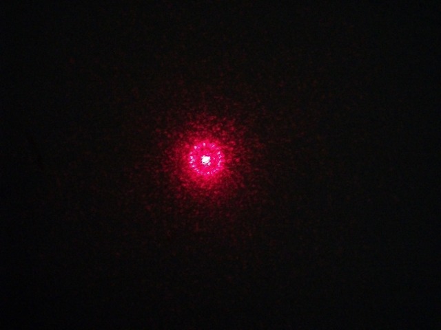
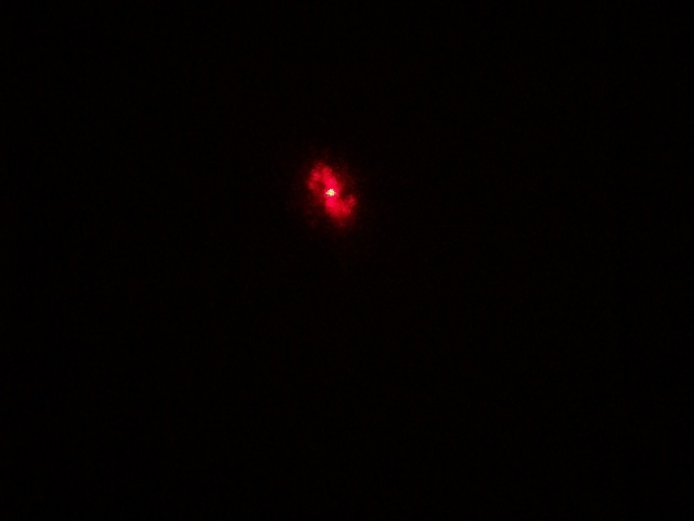
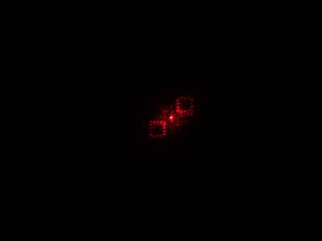
Single
Point
|
Double
Point
|
Circle
(on axis)
|
Reconstruction
|
|
|
 |
 |
Fringes (CGH)
|

|
 |
 |
 |
Source File
|
None
|

|
 |
 |
|
Letter
"A"
|
Another
Circle
|
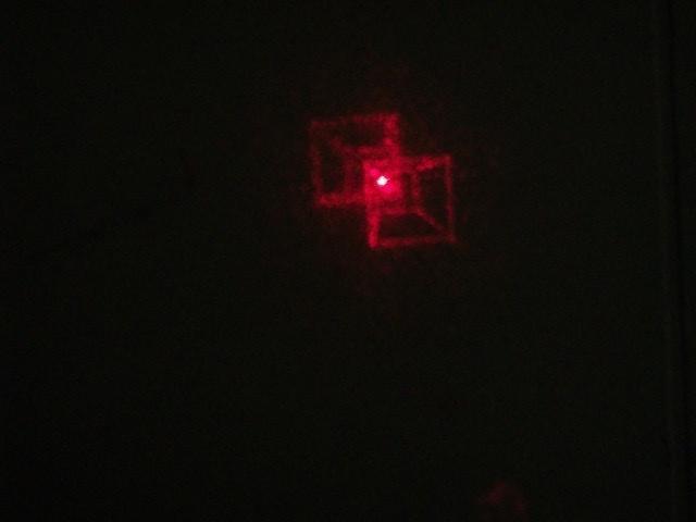
Cube
|
Cube
(more)
|
Reconstruction
|
|
|
 |
 |
Fringes (CGH)
|
|
 |
 |
|
Source File
|
 |

|
JAVA_file
|
JAVA_file |
|
Letter
"H"
|
A
square
|
Circle
(off axis)
|
Triangle
|
Reconstruction
|
|
 |
 |
coming...
|
Fringes (CGH)
|
|
|
 |
|
Source File
|

|

|
 |
XML_file
|
- You can use the Source Files above as input to the
CorticalCafe CGH Construction Kit, or you can edit these or create your
own input files. But keep the total number of pixels in your
image small.
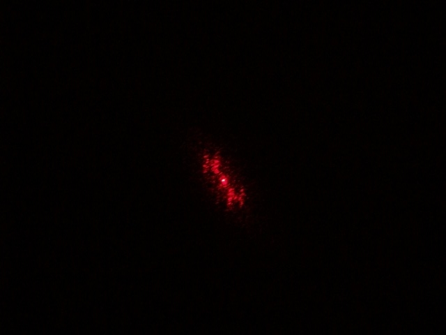
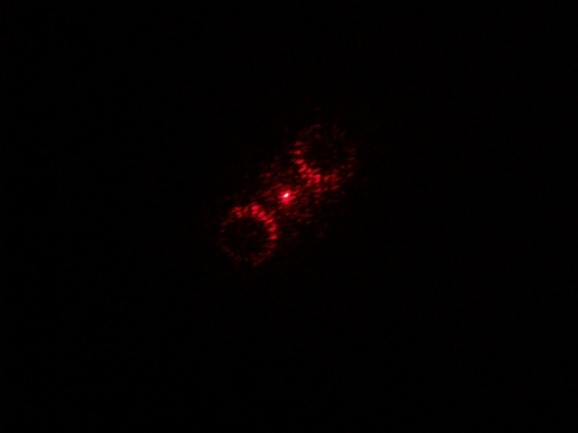
- The reconstructed images in this technique will
always be radially symmetric. That is, you will see a conjugate
image upside down and backwards on the other side of main laser
spot. I took advantage of this with the circle reconstruction
since it is naturally radially symmetric. But the cube
reconstruction clearly shows you the 2 images. Depending on how
the CGH is computed and viewed, You may not be able to separate out the
desired from the undesired image.
- Note the random scatter which accompanies the
images. The transparency becomes a bit cloudy as it goes through
the laser-printer, and creates this background noise which detracts
form the images.
- The computed holograms sometimes have aliasing and
artifacts. This is a function of using a binary output device,
the laser printer. It looks neat, but undoubtedly causes some
issues in the reconstruction which have been addressed in CGH
literature.
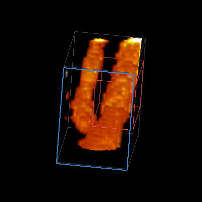
- You can't compute the cube yet using my online
program, but you can download the fringes and play with it. In
the animation above, you can see that moving the cube through the beam
allows you to rotate the projected image of the cube in
3-dimensions. Groovy.
The
Diffraction
Grating
A Diffraction Grating is the great grand-daddy of holograms and a good
place to understand what is going on here. It is simply a set of
very closely spaced parallel lines. If you print the gratings on
this page, you should see a set of alternating transparent and black
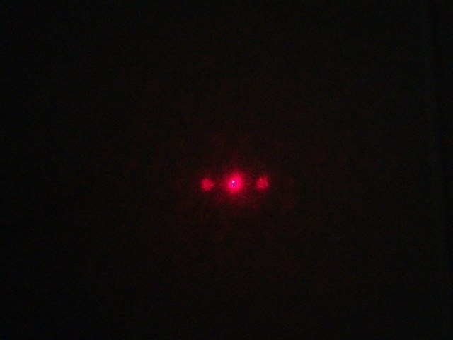
lines on your film. When the laser passes through this pattern,
the beam is diffracted, and the light is spread out on the
screen. Ideally, you should see a set of dots which repeat
on either side of the main laser beam like this. If the
dots aren't clear, then the light isn't being diffracted
efficiently, and the quality of your CGH will suffer big-time.
The 600 DPI grating represents the closest lines that your printer can
print, hence, it also represents the largest projected image for this
technique. Your projected CGH's will be this size or
smaller. Of course, when using the diffraction grating, you can
increase the distance between the hologram and screen to increase the
image/dot size. But this doesn't really help our CGHs since the
hologram calculation requires the inclusion of a focal distance.
And increasing this focal distance makes the object smaller which
offsets the size increase.
The 300 DPI grating doesn't push your printer quite so hard as the 600
DPI version. Because the lines are farther apart, the diffraction
spots on the wall are closer together, and an image printed at this
reslution will be smaller.
If the 600 DPI grating looks bad, but the 300 DPI grating looks good,
then your printer is having difficulty printing at 600 DPI. In my
experience, 600 DPI gratings tend to be "blotchy", perhaps
from variability in toner particle size . You can directly
examine the gratings with a magnifying glass to see the quality of your
printer in drawing the grating lines. If you don't see parallel
lines at all, but rather some cross-hatch type pattern then
your printer settings or driver are problematic and more complicated
CGH attempts are almost certain to fail.
About Printers
In the course of my experiments, I've encountered quite a number of
printer issues. We're pushing the limits of printer technology
and we care about pixel placement accuracy more than any printer
manufacturer ever imagined. Any of the numerous enhancements that
the manufacturer added to the printer firmware because they usually
improve image quality are pretty likely to ruin your chances of getting
a good reconstruction. My printer tips are as follows:
- Just because a printer advertises 1200dpi
resolution is no
guarantee that every single dot in the image will accurately correspond
to a dot in the output. Don't assume that any resolution mode
prints accurately without an experiment to demonstrate it.
- To quickly detect whether your printer is accurately
reproducing your images, try printing a symmetric test pattern (the
"double point" pattern above is excellent) at all available
resolutions. You'll have to adjust the page size to ensure that
your software doesn't resize the image. I've seen cases where the
fringes print fine at 300dpi (2in across for the "double point"
image) and 600dpi (1in), but at 1200dpi (0.5 in), the pattern was
noticeably different. Some aliasing/moire effects were present
and indicate that image reproduction was not accurate.
- 300dpi is just not fine enough resolution for
reasonable size hologram reconstructions. 600dpi is better, but
again your reconstructions will be small. At 1200dpi, you may be
pushing the limits of technology so that finge printing is not accurate.
- The "Diffraction Grating" is the worst case scenario
since it alternates light and dark pixels. Quite frequently
the pixels are larger than the blank cells and no light is transmitted
through the fringes. You might also rotate the diffraction
grating by 90 degrees, since printer horizontal resolution accuracy and
vertical resolution accuracy are controlled by different mechanisms and
may not be symmetric.
- Add memory to your printer, even if you don't think
you need it. My printer (a brother HL-5340D) would not print at
1200dpi until I added additional memory. It didn't report any
errors, but simply printed in 600DPI mode, despite the fact that the
entire page size was far below the 16MB native printer memory.
- Don't count on the manual or tech support to
help. In my case, Brother technical support was quite wrong about
their description of their own product. From a meaningless
explanation of the differences between "1200dpi" and "HQ 1200dpi" (I
still don't understand the difference!) to outright misinformation
about when additional memory was required, the tech support
representative simply didn't know what was going on. Of course,
if the manual explained this information accurately, I wouldn't have
wasted any time with tech support.
- If your printer advertises "effective"
resolution, I
suggest you look elsewhere since there's almost certainly some
interpolation going on.
- Examine the general quality of your
printer. If your images have inconsistent black levels, you have
streaking, or some other obvious problem, then you probably aren't
going to have much luck.
Problem Solving
Here are some tips:
- All holograms on this page should print as exactly 1
square inch. If your images are not this size, then you are
rescaling (and almost certainly messing up)the image.
- Start with the diffraction gratings. Don't try
anything more complicated until you know that these work.
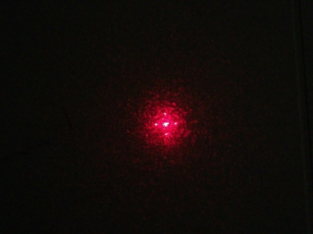
- Transparency film matters. Different brands have
different qualities. Shine the laser through a clear section of
your transparency film and observe the beam. All that noise you
see on the screen interferes with nice quality CGH
reconstructions. Unfortunately, you can see that running a
transparency through the laser printer changes the optical properties
from a nice clear media to a foggy mess.
- Printers matter. Make sure your printer can do
600 DPI. And don't expect good (or any) CGH results if your
normal paper printouts are streaked and dirty.
- For the cube, I printed the image and then took a
picture on 35mm film and used the negative for the laser beam.
This results in a pretty high resolution, high quality CGHs. All
the more power to you if your laser-printer will print at greater than
600DPI. In these cases for the above examples, the CGH plate will
be smaller, but the
resulting reconstruction will be bigger and clearer.
Want
to help?
Here's my wish list:
- Any donations
toward this project will go for improving computing/output resources
and better hosting. See the http://sourceforge.net/projects/cghconstruction page (also for source code, forums, bug tracking, etc).
- Do you have a good suggestion for efficiently
characterizing laser printer output? It would be great to have a
printable template that quickly indicates the quality of an output
device.
Hey, did you try my Online
Printmaker yet?
|