Picaxe Simplest Datalogger
simplest clock picture
Temperature Measurement
simplest clock picture simplest clock picture
Light Detection

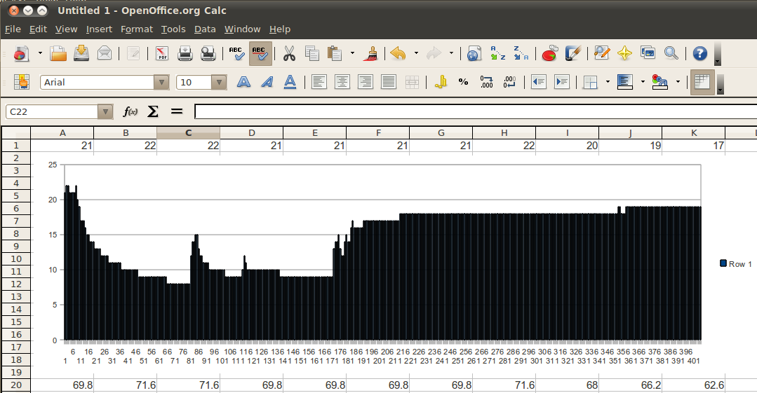
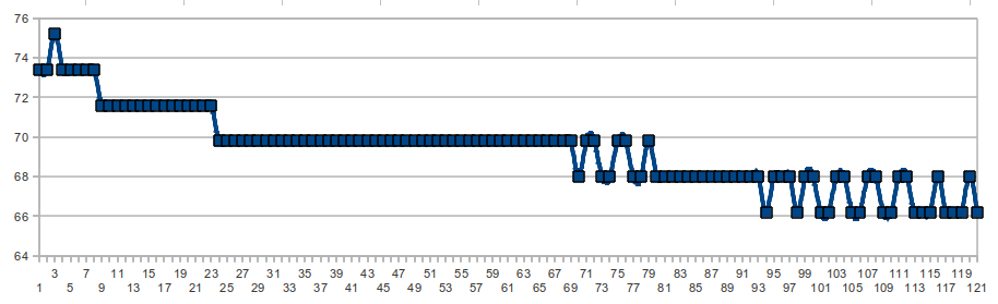
Background
This is a really simple but very flexible way to log data using a PICAXE microcontroller.  Minimal parts, flexible data samplng, great battery life, and simplicity of data export to a PC were the important design considerations.  This logger can read a voltage, a resistance, the internal temperature sensor, an external DS18B20 temperature sensor, or even monitor its own power supply.  It is entirely controlled via the same serial cable that is used to program the PICAXE. The only parts are the PICAXE, an LED to indicate that the logger is functioning, and a connection to the device being monitored (unless you use the internal temp sensor).  Pretty amazing that you can monitor almost anything for $5, and using a single low-cost DS18B20 adds accurate temperature measurement.

I hacked this together quickly to monitor the charge state of a battery hooked up to a solar panel.  Then I used it to monitor the temperature change in a room from the furnace, and then looked at changes in ambient light levels due room lights and daily sunlight.  I kept adding features to this project to make it completely standalone and configurable over the serial line.  It now includes battery level indication, extremely efficient power use including a low power mode, and a range of input configurations.


Data logger input configuration
If you want to monitor a voltage which is greater than the supply voltage of the PICAXE, then you should use a voltage divider (simply 2 resistors in series) to reduce the voltage being sampled.  The internal temperature sensor is nifty, but not very accurate, and it is very dependant on the power supply voltage. If you use the interal sensor, be sure to read up on the READINTERNALTEMP command and adjust this code for your supply voltage.  The DS18B20 provides a far superior method of temperature measurement at the cost of a single low-cost component.  Monitoring the power supply voltage is not likely to be very interesting unless you are running this data logger off a source which itself changes voltage, like a solar powered garden light.


Sampling
The RAM of a PICAXE 20M2 will hold 483 single byte samples.  At 1 minute intervals, this adds up to 8 hours of data.  At 15 minute intervals, this is 5 days of data.  And if you choose 2 hr samples, you can collect more than a month of data.  The data logger also has a low-power mode which reduces current consumption to about 200uA.  A 2000mAh battery capacity is pretty reasonable for AA cells, so you should easily be able to collect many months of data.  Note that using the low-power mode may make the unit appear nonresponsive since it's sleeping much of the time (see Low Power Mode below). In any case, make sure that you download your data before the batteries run out, since data is stored only in RAM.


Calibration
  • Temperature
    • The internal temperature measurement is highly dependant on the power supply, Vcc, and probably not worth too spending too much time on.  If you want accurate temperature measurements, use a DS18B20. This sensor automatically reads in degrees Celsius.
  • Voltage
    • ADC readings are dependant on knowing the supply voltage, Vcc. The "calib" command allows you to calculate Vcc and is displayed on data [D]ump.
      • VccCalc = 261/calib.
    • Once you know Vcc, it's easy to convert ADC readings into voltage, Vin, since a full scale ADC reading of 255 equates to Vcc
      •  VinCalc=readADC*VccCalc/255
    • Example
      • My VMM says I am using a 3.88v supply for Vcc. The calib=66. This means VccCalc=261/66=3.96v. VccCalc is pretty close to VccMeasured.
      • So applying a 2.41v reference as Vin, the readADC=158. This means VinCalc=158*3.96/255=2.45v. Again, VinCalc is reasonably close to VinMeasured, at least within the accuracy of my $5 VMM.
  • Resistance
    • The ADC measurement reflects the voltage across an unknown resistor, Rin, which is the lower half of a voltage divider circuit. The upper resistor is the internal pullup resistor in the PICAXE, as enabled via a "pullup" command. I'll have to read up on the values/tolerances, and work through the math to explain how to calibrate resistance readings.  Stay tuned...


Exporting Your Data
  • Dump your data to the serial terminal using the [D]ump command.
  • Copy the string from the terminal window and paste into a spreadsheet. 
    • In OpenOffice (LibreOffice) you can click the cell you pasted, and use the Data>Text-To-Columns function to give each comma-separated-value a different cell.
    • To graph:  Select the row, and Insert>Chart to graph the values.
    • To transpose so data is in columns instead of rows: Highlight the entire row, and cut (crtl-x). Then right click a cell and "paste-special".  Check "Transpose" before clicking "ok".
If you want to use a terminal program other than the PICAXE programming editor or LinPad to access the datalogger, you can without any issues.  Just be sure to connect at 4800,n,8,1. 

simplest clock picture
(click to enlarge)


Quickstart Guide (eg, measuring 24 hours of temperature via a DS180B20)
  • Download the program via the serial cable.  It will start logging automatically. 
  • Open the terminal window with F8.  It shows a summary of datalogger activity (eg, # of sample points collected, sampling interval in seconds)
  • Choose an input configuration:  Resistance, Voltage, Temperature, or Power (see code for pinout definitions)
    • We will connect a DS18B20 on pins B.1, B.2, and B.3 as in the schematic
    • If you're using Voltage or Resistance measurement, connect pin 'vIn' to the voltage or resistance to be measured, and use pin 'gndPin' as a common ground. 
  • Choose a sampling interval, set the sensor, and you're logging data
    • Press [5] to select 300sec sampling intervals, [T]emp to select the external temp sensor
  • Disconnect and move the datalogger to its position in the field where it will monitor data
  • After the desired duration (eg, 24 hrs), reconnect the datalogger to the PC and use the [D]ump command to retrieve your data
  • Process as desired in your spreadsheet

Command Reference
  • Datalogger commands:
    • C - [c]lear memory and restart normal logging
    • D - [d]ump memory and params to terminal via serial link
    • S - [s]top, enter low power mode; cycle power to start data logging again (do this to enable the PICAXE to receive program downloads)
    • R - configure input to read a [r]esistance
    • V - configure input to read a [v]oltage
    • I - configure input to read the [i]nternal temperature sensor
    • P - configure input to read the [p]ower supply
    • T - configure input to read DS18B20 temperature sensor
    • # (0-9) - adjust sampling interval (see table below)
    • L - Enter (L)ow power mode; see text below
    • Z - reset device (equivalent to cycling power)
    • H - [h]elp

Sampling Rate Table
Keyboard Command
Sampling interval
Max Data Collection
1
5 s
40 min
2
15 sec
2 hr
3
30 sec
4 hr
4
1 min (60 sec)
8 hr
5
5 min (300 sec)
40 hr
6
15 min (900 sec)
5 days
7
30 min (1800 sec)
10 days
8
1 hr (3600 sec)
20 days
9
2 hr (7200 sec)
40 days
0
6 hr (21600 sec)
4 months


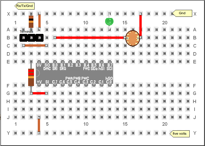
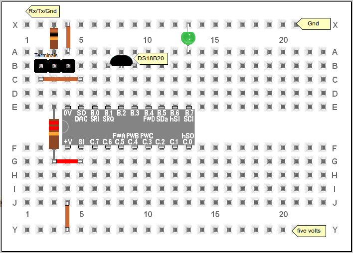
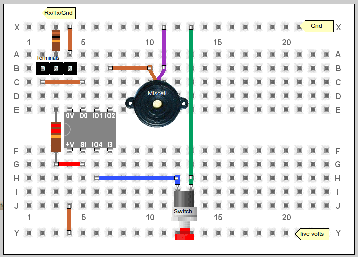
Help!  I can't download a new program to my PICAXE!  (No, your PICAXE isn't broken!)
Because this program uses the serial port, it becomes "disconnected" from the normal PICAXE program download routine.  This means that if you try to download a new program to the PICAXE when it is already running this program, the progamming will fail, and you might be tempted to think that your PICAXE chip can no longer be reprogrammed.  This is *not* the case.  If you want to reprogram your chip, just issue the (S)top command from the terminal, which will reconnect the standard PICAXE firmware routines, and allow normal programming again. 

You can, of course, always program a PICAXE immediately after applying power to it, because the PICAXE firmware checks for a new program download over the serial line before it starts running the program already in memory.


Low Power Mode  (Another reason you might mistake your PICAXE for dead!)
In low power mode, the unit NAPs often, so interval timing is less accurate.  But current consumption is reduced from approx 1 mA to 200 uA which means the batteries will last substantially longer. Unfortunately, "low power mode" can contribute to the impression of a broken PICAXE chip, since when low-power is enabled, the data logger will only respond to a PC command via the serial port if it is issued within 1 second following an LED flash.  These flashes occur approximately every 10 seconds.   I could automatically enable the low-power mode when the memory is full, or after 3 minutes without a PC command, but I've fought against this feature creep to avoid any confusion.  Low power mode only occurs if explicitly enabled via the [L] command.  It is automatically disabled as soon as the datalogger receives a command from the PC.


The following schematic/layout drawings was generated from this file using PEBBLE (Picaxe Electronic Bread Board Layout Emulator - V3.1).


simplest clock schematic


simplest clock schematic

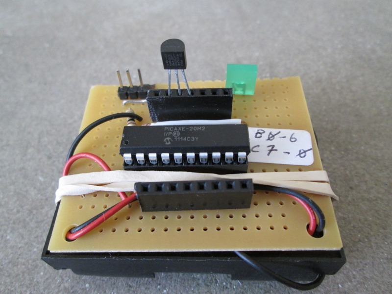
(click to enlarge)

Parts count:

  • 1 Picaxe 20M2 microcontroller
  • 2 resistors (10K, and 22K; for in-circuit programming)
  • 1 3-pin programming header
  • 1 LED
  • 2 female header sockets (7 pins, and 8 pins)
  • misc wire, DIP socket, a battery holder, veroboard
  • if desired, some sensors (eg, a light dependent resistor, DS18B20 temperature sensor, solar cell, etc.)


Construction
My schematic is above, and here is the code (500 Lines, approximately 1000 bytes, and plenty of comments).  My style/documentation is pretty rigorous, but I strongly advocate good coding practice regardless of the machine; all software only becomes more obfuscated over time.

You should be able to build this datalogger on a solderless breadboard in just a few minutes.  Soldering a more permanent version on stripboard like the one in the pictures above won't take too much longer.  As you can see, I'm fond of using female programming headers to access the I/O ports instead of soldering components like the LDR or DS18B20.  This provides reasonable mechanical construction, but also great flexibility when I decide I want to use the project for something else.  I've saved hours of time by recycling projects this way.  And if I do have some hardware soldered in place, I can quickly identify the project and electrical connections by reading the code identification (via the serial terminal) that executes as an initial command in each one of my programs (see code).


This code is explicitly released under the GPL. And this page is licensed under a Creative Commons Attribution 2.5 License.  

Email me if you find this project interesting.  I'd love to hear how it is being used, especially if it is useful for science education.  Link to this page if you find it useful, and I'm happy to link to your pages if you have some info on how you're using this circuit.

Warning, may cause loss of time. This project is provided without any warranty and probably isn't suitable for anything.

Back to Picaxe Projects