| Magazines: AutoSpeed | Rallysport | V8X | Silicon Chip | Shopping: Property | Cars | Fishing |
 |
| Current Articles | | | Archived Articles | | | Search | | | Free Preview | | | Register |

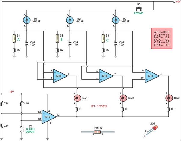
Electronic conjuring trickThis circuit was developed in response to a request from a Scottish conjurer. He wished to place four small, coloured balls on stage, each a different colour, and then invite members of the audience to come up and put one in their pockets. He wanted to be able to tell who had which colour without actually seeing the balls they had taken. This he could do if he knew the sequence in which the balls had been taken. The trick is implemented here with three balls instead of four, since this is simpler by an order of magnitude. At first glance, three sets of three LEDs could be used to give an indication of the order in which each ball was taken. However, such a circuit would be complex, with a readout comprising nine LEDs in all. With a combined analog and digital approach, the number of LEDs can be reduced to just three. There are six possible sequences in which three balls could be taken. Supposing that we label the balls A, B and C. Ball A could be taken before ball B and vice versa. Ball B could be taken before ball C and vice versa. And ball A could be taken before ball C and vice versa. If each of these orders of priority can be recorded with a single LED (the LED being illuminated if the second ball is taken after the first), the trick is complete. The trick commences with the charging of the three 47μF capacitors through pushbutton switch S5. Initially, each of the reed switches (S1, S3 & S4) are closed by a magnet mounted inside each of the coloured balls. This means that as soon as S5 is released, the capacitors begin to discharge. With the component values shown, discharging takes almost a minute; therefore all three balls must be taken within this time frame (the capacitor values can be changed to suit). A JFET input op amp with high input impedance was chosen for IC1 so that discharging through the inputs of the IC is negligible. When a ball is removed, the associated reed switch opens and the discharging of the capacitor in that circuit is "frozen", performing a simple sample-and-hold function. IC1a, IC1b and IC1c compare the remaining charge on each capacitor, with the resultant sequence appearing on the three LEDs. The conjurer may either remember which sequence of illuminated LEDs corresponds with each sequence of coloured balls or he or she could work out the logic directly each time, perhaps "thinking out loud" about the three orders of priority displayed by the LEDs. The conjurer might not wish to risk having the LED readout permanently "on", therefore the LEDs are enabled only when two metal points (perhaps pinheads) are touched with a moistened finger. Comparator IC1d provides this function, with its output normally "high" until the non-inverting input is pulled towards ground by finger contact on S2. Since the trick relies on consistent discharging of the three capacitors, these capacitors, together with the associated diodes, resistors and reed switches, should all be matched. If the trick is performed with only a moderate level of expertise, it should baffle and astound. Thomas Scarborough,
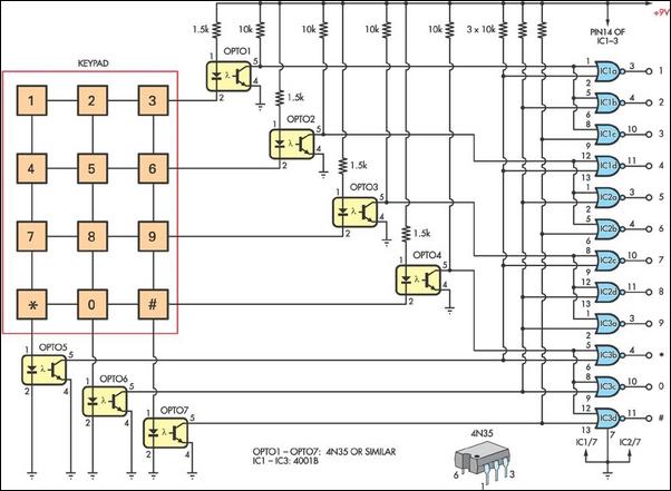
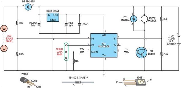
Keypad decimal encoderThis simple design can be used as part of a combination lock or other controller circuit, where an individual output for each button press is required. It uses a conventional keypad with 12 keys and 7 pins (eg, Jaycar Cat. SP-0770). Pressing a button connects the associated row and column lines together. Each row and column output is connected in series with the LED of a 4N35 optocoupler. The optocoupler outputs drive a matrix of 4001 NOR gates, which in turn encode the button press to provide a logic high level on just one of the 12 outputs. For example, pressing button "5" connects the LEDs in OPTO2 & OPTO6 in series. This completes a circuit from the +9V rail, through a 1.5kΩ current-limiting resistor and the two LEDs to ground. Both optocoupler transistors conduct, pulling the inputs of IC2a low. The result is a logic high at the "5" output, with all other outputs remaining low. Peter Howarth, PICAXE-controlled solar fountainAdd a solar-powered fountain to your fish pond or garden water feature with this unique PICAXE design. The prototype was constructed with a low-cost 12V DC camping shower pump (available from Jaycar), a 2W solar panel and a 12V 7.2Ah SLA battery for energy storage. A PICAXE-08 micro controls the fountain pump, switching it on for 30-second bursts whenever sufficient battery power is available. Pulse-width modulation (PWM) of the pump motor is used to reduce average current, providing a more appealing water flow as well as longer running time. The voltage from the solar panel is divided down by 18kΩ and 8.2kΩ resistors before it is applied to a PICAXE digital input on P3 (pin 4). When the panel output is higher than about 8V, the input will read high, whereas lower voltages will read low. The program uses this input to differentiate night from day, eliminating the need for an LDR sensor. Two resistors also divide the battery voltage down before it is applied to the PICAXE analog input on pin 1 (leg 6). The program periodically reads this input and using simple logic, chooses one of several strategies. If the battery voltage is less than about 11.4V, the pump is not driven and the program "sleeps" for 10 minutes. Between about 11.4V and 14.5V, the pump is driven for 30 seconds followed by either 3, 5 or 10-minute rest periods. Above 14.5V, the pump is again driven for 30 seconds but the previous rest period is halved. If the voltage is still above 14.5V the next time around, the rest period is halved again, and so on. This prevents the battery from being over charged, as the power used by the pump will always be higher than the power produced by the panel. PWM output from the PIXACE on As you can see, the pump will turn on more often the sunnier it
is. I have run this system for over Robert Gatt,
|
|||||
|
|
|||||
|


